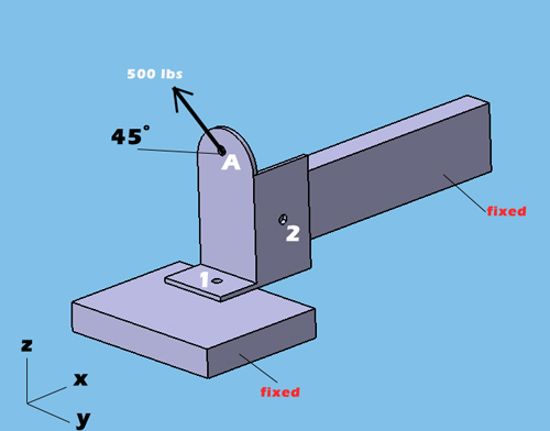
When you use my rigid body equilibrium calculator, it is more convenient to define the load application points coordinates (point A) as 0,0,0 in x,y,z coordinates. From point A (0,0,0) to each attachment points, you need to measure the distance in x,y,z and write down the distance in the attachment points coordinates section. Make sure that you measure distance paying attention to positive or negative distance with respect to coordinates system. In the example below, the number 1 attachment point is located -0.5in (negative) in X axis from the point A (0,0,0) while the number 2 attachment point located 1in(positive) in X axis from the point A (0,0,0). You need to perform this for each axis to find the distance for each point. Also make sure that, your load application is inline with this approach paying attention to coordinate system. In the example below, Z component of the 500 lbs is in positive direction in Z axis while Y component of the 500 lbs, is in negative direction in Y axis. That is why Z load is entered positive and Y load is entered negative in the calculator for point A. Bottom line is don't forget to put negative or positive sign


