Bracket Design Loads, Reaction Forces Under Applied Load
- Details
- Umut Aksoy
- Rigid Body Analysis - Reaction Force Calculator
- Hits: 11816
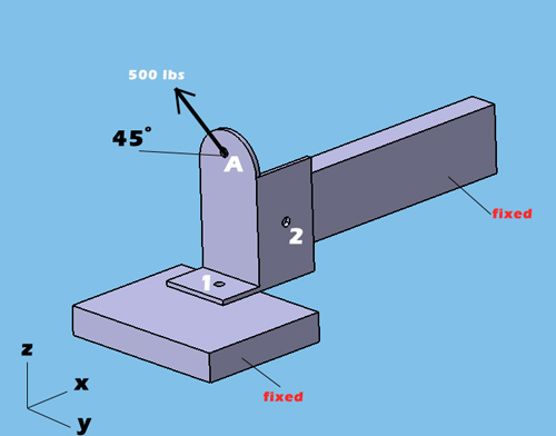
When you use my rigid body equilibrium calculator, it is more convenient to define the load application points coordinates (point A) as 0,0,0 in x,y,z coordinates. From point A (0,0,0) to each attachment points, you need to measure the distance in x,y,z and write down the distance in the attachment points coordinates section. Make sure that you measure distance paying attention to positive or negative distance with respect to coordinates system. In the example below, the number 1 attachment point is located -0.5in (negative) in X axis from the point A (0,0,0) while the number 2 attachment point located 1in(positive) in X axis from the point A (0,0,0). You need to perform this for each axis to find the distance for each point. Also make sure that, your load application is inline with this approach paying attention to coordinate system. In the example below, Z component of the 500 lbs is in positive direction in Z axis while Y component of the 500 lbs, is in negative direction in Y axis. That is why Z load is entered positive and Y load is entered negative in the calculator for point A. Bottom line is don't forget to put negative or positive sign
Read more: Bracket Design Loads, Reaction Forces Under Applied Load
How to Calculate Module of Elasticiy in Tension and Flexural
- Details
- Umut Aksoy
- Stress
- Hits: 8546
The modulus of elasticity (= Young’s modulus) E is a material property, that describes its stiffness a nd is therefore one of the most important properties o f solid materials. When a material deforms elastically, the amount of deformation likewise depends on the size of the material, but the strain for a given stress is alwa ys the same and the two are related by Hooke ́s Law (stress is directly proportional to strain):
σ = E × ε
σ is stress
E is modulus of elasticity
ε is strain (unitless)
Elasticity module is calculated as follows; dividing stress by strain.
E = σ / ε
What is strain in Tension?
Strain in tension is defined as the change of the length divided by the original (initial) length

ε = ( Δl ) / lo (strain under tension)
Δl = Change in Length
lo = Original Length
How about what is the strain in Flexural stress?
When the material is under bending load, strain is calculated as dividing the distance from the neutral axis by the curve radius.

ε = y / r (strain under bending)
How to Calculate Modules of Elasticity?


E = Modules of Elasticity (Young's Modules)
W = Applied Load
l = distance between supports where the beam bends
w = width of the beam
h = height of the beam
d = deflection
Which Beam Bends More? Simply Supported or Both End Fixed Beam?
- Details
- Umut Aksoy
- Bending Stress
- Hits: 7672
Let's assume we have exactly the same profile (rectangular or square or triangle or cylindrical etc.) beam under bending load. The reason I say exactly the same profile is because I would like both of the beam profile to have the same moment of inertia. The only difference between the beam profiles are one of them simply supported and the other one is fixed on both ends as shown below. If you apply the same force, which one bends more?
Both Ends Fixed Beam


One End Fixed Other End Simply Supported Beam


Both End Simply Supported Beam


Since both beams have the same E (module of elasticity) and I (Moment of Inertia) due to same beam profile, you can see that max deflection (△max) on a simply supported beam is 4 times bigger compared to both ends fixed beam.

